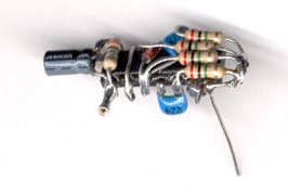

If you'd like to understand how the MicroCore works, study Solarbotic's tutorial on the MicroCore here. You don't really need to understand how this all works.
You may want to build the Motor Driver first to get used to freeforming and soldering and then tacle the MicroCore. It's easier to de-solder and fix suff on the Motor Driver than on the MicroCore.
Study the Full MicroCore Schematic below so you get an idea of what we're going to do. Don't worry if it seems too complicated because I'm going to fill that schematic in gradually in the order that we're building it.
We'll build the MicroCore in a logical order. That'll make it easy to solder the parts so the first parts you solder are not in the way of the next ones.
I recommend that you follow this procedure and later, find your own personal process if you feel that you can improve it. But I highly recommend that you follow this one for your first MicroCore.
First you should look at the parts list here.
Click on any image to see it full size.
The first step is to prep the 74AC14 IC.
Clip off the THIN part of the IC's "legs":
When you're done, it should look like this:
Tin all the IC's connectors. -- Tinning means to put a bit of solder on a metal part to make it easier to solder another part to it. "Paint" a bit of Flux paste onto the connector, then put a bit of solder on the tip of your Soldering Iron and touch its tip to the connector. You'll see the flux go up in smoke and then you'll have a nice little bead of solder on the connector.
I use this technique for every connection I make... first "paint" some flux on each part, then dab a bit of solder on the tip of my Soldering Iron, then put the two parts together and last, touch the tip of my soldering iron to the parts. -- The solder seems to Jump from the iron's tip to the parts. This makes a very clean connection with a small amount of solder.
The most important tip I can give you is to use very little solder for each connection. Remember that you will solder many different parts to the same connector (one on top of the other) so if you start with a big glob of solder, the next time you solder another part to it, it'll have too much solder and you'll end up soldering bridges where you're not supposed to. So keep it clean and use tiny bits of solder.
Notice the beads of solder on each of the IC's connectors in the image below:
Now we build the Reversing Circuit:
Using the technique described above and a set of Helping Hands, solder a piece of one strand wire to Pin 2. I use Radio Shack's 4 strand, 24-gage, Telephone Wire. It gives me 4 solid wires (Red, Black, Green, Yellow).
Bend the wire over and around the chip and solder it to Pin 13.
This completes the Reversing Circuit.