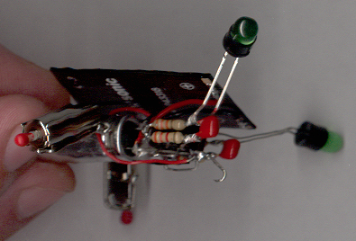
Click here to see a Video of a Fred Photopopper in action.
The sun wasn't so bright when I took this video. The sky was covered with a grey haze. Under bright sunlight, this popper jumps much more frequently and more violently. I plan to take another video with him under bright sunlight.
I put up a page of Robots built by others using these tutorials. Click here to see all the photo submissions.
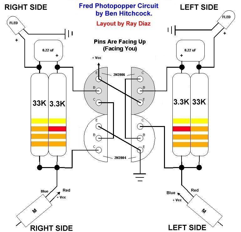
This is my layout of Ben Hitchcock's Fred. It's a combination of Andy's FRED Tutorial and Chiu's Photovore Tutorial.
I like this Solar Engine layout because it's vertically symmetrical (when looked from above or bellow) and a bit more compact. It's a bit harder to build than Andy's and it's tougher to troubleshoot if you mess up because the two SE's are glued together into one unit -- Andy's are two completely independent SE's that can be un-soldered and replaced very easily. But my layout looks cool, no?
Click HERE to see the Layout I came up with.
Click HERE to see Ben Hitchcock's tutorial and info on the FRED Photopopper.
These are the parts you need. (Click on the image below to see it full-size).
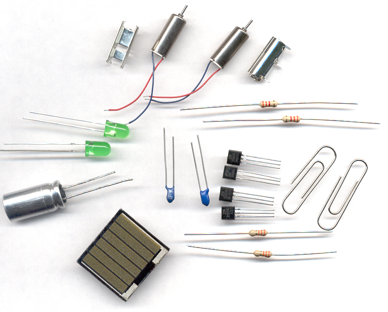
Click Here to see the part numbers and suppliers etc.
You can order Fred kits and parts from Andy's Solar-Bugs. His prices are great. (A whole Fred kit for $9.00/US!).
I recommend that you print out the Wiring Diagram before you begin, read through all tutorial
while you refer to the diagram to minimize the chance of errors.
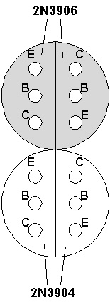
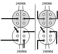
OK. Here's what you do... Glue the two 2N3904's together face to face, (flat side to flat side). Do the same with the 2N3906's See the next picture.
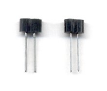
I mark the 2N3906's with a dab of Liquid Paper (correction ink) before I glue them together. If you don't mark them somehow, you'll probably loose track of which is which. This would ruin the solar engine, of course.
I use correction ink because I scrape it off with my finger-nail when I longer need it, leaving absolutely no trace of the white stuff.
Now, glue the 2N3906's and 2N3904's together like in the following pictures. The 2N3906's will be on the top in throughout the tutorial. (Click on the middle picture below to see it full-size).
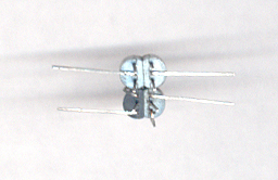
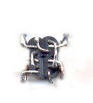
Bend pin E of both your 2N3904's down and over forming an "L" on top of the Transistor, solder them together at the tips as shown in the next image. You'll have to clip them so meet at the tips as shown below. (The image shows bottom and top views side by side).
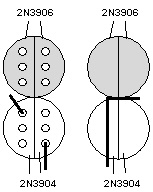
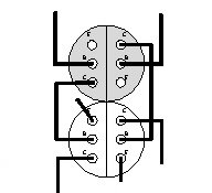
Bend the pin B of both your 2N3906's down flat (to each side) and then up in an "L" shape as shown. Then bend both C pins of the 2N3904's down flat and in an "L" shape. Refer to the Wiring Diagram often to make sure you bend the right pins. If you make a mistake and try to bend it back, it'll probably break and ruin your whole Solar Engine.
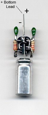
No matter what you do, you'll leave a space between the two E pins and the Transistors. This is actually good because you'll push the Positive Lead of the 3300 uF Capacitor through that space and solder it to the two 2N3906 E pins. See Here.
Now bend and solder leads 2N3906-C to 2N3904-B, on both sides of the Solar Engine. Again, see the pictures below and the Wiring Diagram for reference.
Now, follow the next steps (twice) to build two "modules" you'll add to the Solar Engine:
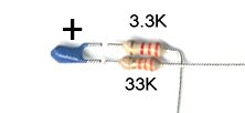
The two completed "modules":
Solder them to the Solar Engine as shown. (2N3906-B goes ton the intersection of .22 uf Cap and 3.3k Resistor, and 2N3904-C goes to the intersection of 3.3K and 33k Resistors, see the Wiring Diagram).
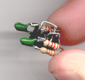
(I painted the 0.22uF Caps green to match the Green FLEDs I'm going to use).
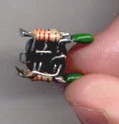
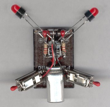
Here's the 3300 uF Cap inserted into the Solar Engine. Solder Cap's the leads where they touch the Solar Engine's leads
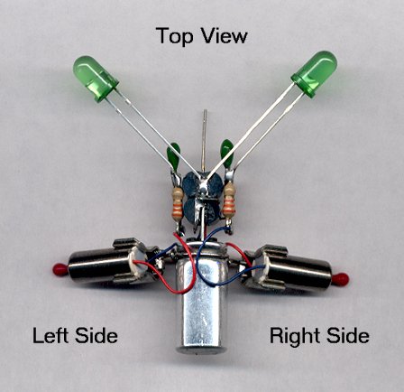
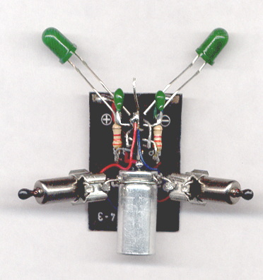
Top View:
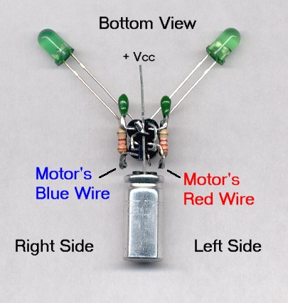
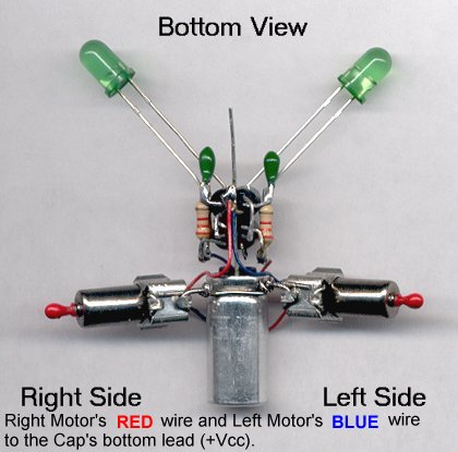
Bottom View:
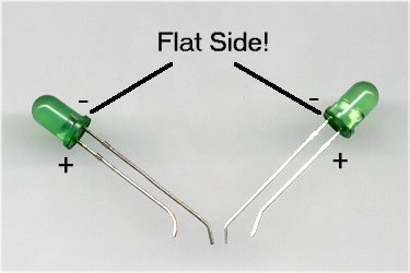
Find two FLEDs with the same (or very similar) resistance. Andy's way is the best. Click here to see.
Bend the leads of the two FLEDs as shown. See the next two pictures and the Wiring Diagram.
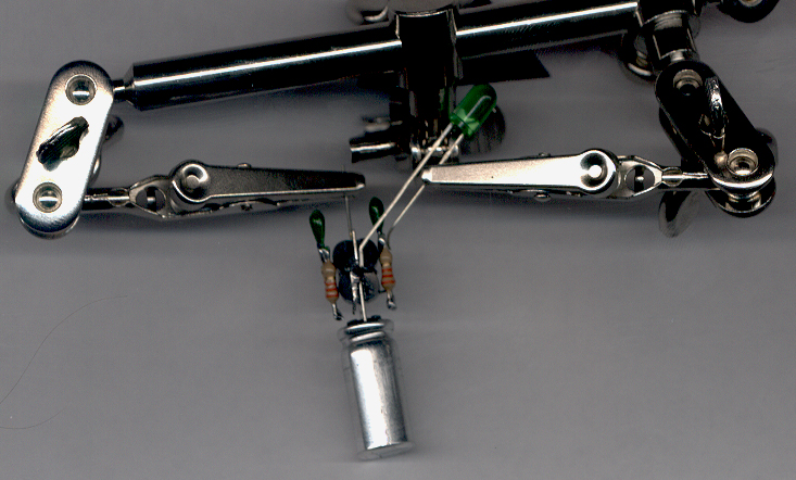
This is probably the the toughest soldering job of the whole project so use your Helping Hands. It's practically impossible to solder the FLEDs straight using only your hands. -- Of course you can clip the FLEDs leads short and give your bug a different look.
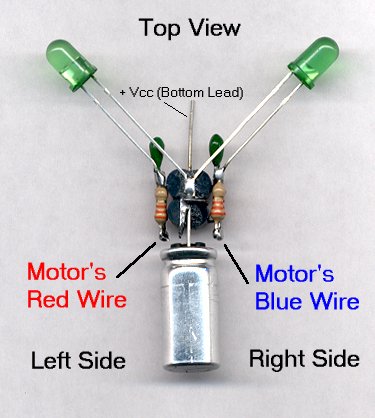
Compare the next few images to the Wiring Diagram before you solder the motor leads.
Now go to the Pager Motor Mount Tutorial... before you go on.
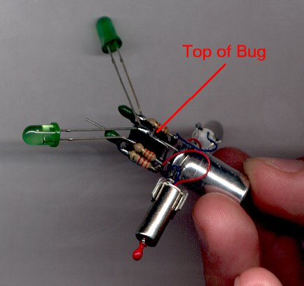
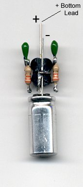
Bend the Positive lead of the 3300uF Cap to make a skid. (See the next picture).
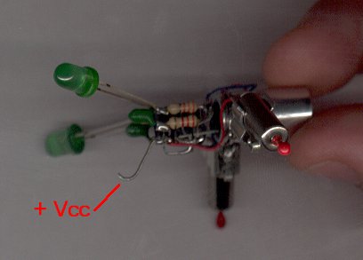
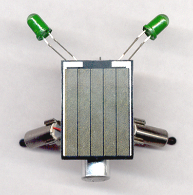
Installing the Solar Cell
This part is rather tricky because there's so little space between the Solar Engine and the 3300uF Cap. -- You can leave more space here if you like, but it just looks better if you keep it all nice and tight.
Let's take it one step at a time.
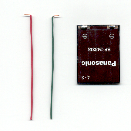
I use Solid Core 24 gage wire for all my BEAM projects.
Bend the two leads as shown in the next picture, and put a dab of solder on each of the Solar Cell's terminals (Positive and Negative). Be very careful not to overheat the Solar Cell.
You may want to unplug your soldering iron and wait for it to cool down a bit and then put it to the solder and lead.
Solder the leads to the Solar Cell and bend them in the following shape.
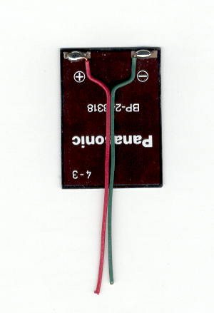
Bend the Leads downwards, at a 90 degree angle ("L" shape) and pass them through the space between the 3300uF Cap and the Solar Engine. leave about 1/4 of an inch space between the Cap and the Solar Cell. "Eye-ball it" to figure out where you have to cut the leads and cut them as shown.
Notice that you have to make the Positive Lead a bit longer longer than the Negative one so it reaches the bottom lead. Also note the loop at the end of each lead that'll go around the 3300uf Cap's leads.
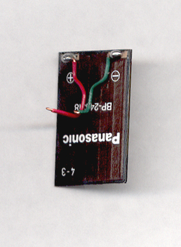
This next shot shows how I bent the Solar Cell upward to reach in there and solder the leads. It's very tight in there and you have to be extra careful not to burn the insulation of the Pager Motor leads, so move them aside as best you can before you solder the Solar Cell leads.
And you're done!
I will put up a troubleshooting page later on with common problems and fixes.
For now, you can go to Solarbotics' photopopper troubleshooting page by clicking here, and here for Ben Hitchcock's.
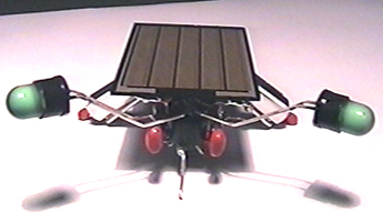
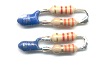
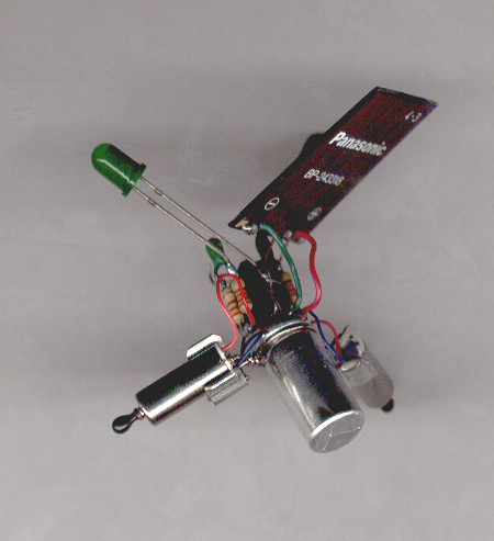
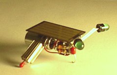
Here are some pics of the finished Popper:
Notice that I painted the FLEDs green. This works as "blinders" for better light tracking and so it doesn't "lock up" so much in strong sunlight.
You can also use heat-shrink tubing (without heating it), wich is great because you can take it off when indoors.
Notice the Heat-shrink tubbing on these pics:
E-Mail me with comments, questions and corrections to this tutorial!
Copyright © 2002 by Ray Diaz. All Rights Reserved.